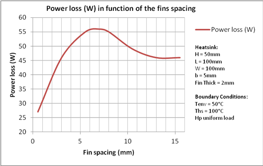
The curved data sets in figure 2 demonstrate the heat flux distribution through the tim2 material determined for the lowest and highest conductivity heat sinks at a value of heat sink width w hs 70 mm and over the full range of h eff they show that even for a package with a 1 mm thick lid made of pure copper the heat flux is.
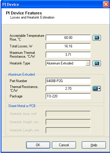
Thermal resistance values heatsink.
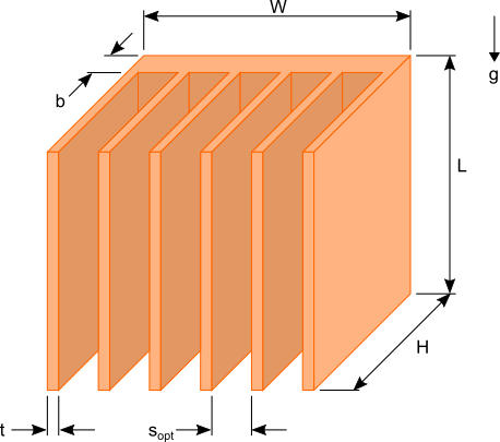
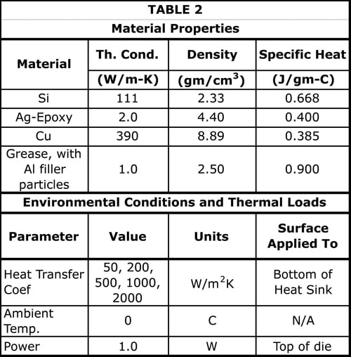
Model dimensions materials and properties.
Absolute thermal resistance r in kelvins per watt k w is a property of a particular component.
For example a characteristic of a heat sink.
The following equation is used to calculate r hs the thermal resistance of the heat sink.
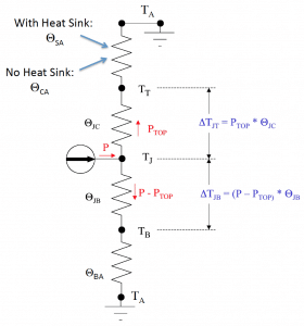
The resistance to heat flow from the junction of the heat generating component through the casing thermal interface material heat sink and finally to environment is represented by the thermal resistance circuit shown in the diagram below.
For the thermal resistances i used the via thermal resistance calculator and approximated the thermal resistance with the vias to be around 4 4 c w using the values from the via calculation tool.
In other words the thermal resistance value ofa chosen heat sink for the application has to be equal to or less than r sa value for the junction temperature to be maintained at or below the specified t j.
With all the parameters on the right side of the r sa expression identified it becomes the required maximum thermal resistance of a heat sink for the application.
Due to recent technological developments and public interest the retail heat.
A thermal interface material or mastic aka tim is used to fill the gaps between thermal transfer surfaces such as between microprocessors and heatsinks in order to increase thermal transfer efficiency it has a higher thermal conductivity value in z direction than xy direction.


